In this article we'll take a close look at how test fixtures assist in electronics testing, and how it has evolved over the years.
What is a Test Fixture?
In the electronics industry, test fixtures play a vital role in the development and production phases. Take any electronics project under development, and you will need a system to test its real-time operation to detect defects and errors. It can be a fault with a soldered joint on a printed circuit board (PCB) or it could be a software issue, which many of today’s devices are running. Using a test fixture, which creates a testing environment for a device under test (DUT), you can find faults and create an iterative process for better development.
In the production phase, there is a great need to be able to functionally test components separately, such as displays, memory modules, cards, or IC chips to sort them and to make sure only highly performing components are proceeding to the assembly line, thus reducing the risk of assembling faulty units.
In today’s digital age, test fixtures have evolved rapidly in both form and technology. The benefit of using elastomeric-based test fixtures is that they provide reliable and strong connection between the DUT, instrument, and fixture, while the contact itself is soft and does not damage the delicate contact pads. The more reliable the connection, the better and faster is the test cycle. The elastomeric approach also strengthens the concept of custom test fixtures that are available in the market to cater to the growing needs of design engineers.
Testing Fixtures in Electronics
Test fixtures can be used across applications so that any electronic module can be checked for faults prior to its final assembly stage. In essence, a test fixture creates a suitable environment for the device to be tested. This can be a device under test (DUT) or equipment under test (EUT). Regardless, the idea behind the system is for the DUT to stay in place and receive external stimuli in the form of test signals.
Test fixtures enable a temporary, non-damaging, electrical connection between a DUT and a test equipment. The way the DUT or EUT or their individual elements responds to these test signals allows engineers to detect issues and correct them.
The advantage of such functional tests is that defects and errors can be detected before a component goes into commercial production. The defect could be as minor as a bad solder joint in an isolated area in the electronics board or a dead pixel in a display. If it is not detected early on, it can cause huge losses and embarrassment to the producer. Imagine a cell phone manufacturer having to recall its latest units because of faulty displays.
In a general sense, such test fixtures can be used to test the following types of DUTs:
While general-purpose test fixtures such as bed-of-nails (BOD) configuration or in-circuit test (ICT) and Smart Fixtures have existed for years, modern applications require test fictures with more edge, efficiency, and utility. This has resulted in automated testing involving computers that aim to reduce human error and completely isolate and fix the defects/errors that are found.
Types of Test Fixtures
The type of test fixture depends on a variety of factors, mainly the DUT and the type of testing it requires. In that regard, here are some of the most common types of test fixtures:
In-Circuit Testers
Also known as an ICT, test fixtures are used to test board assemblies like PCBs that involve the use of integrated chips (ICs) and other embedded systems technology. The challenge with such test prototypes is that they are densely populated with connections and solder joints. The contacts and the overall environment need to be extremely in sync to detect even the tiniest of errors.
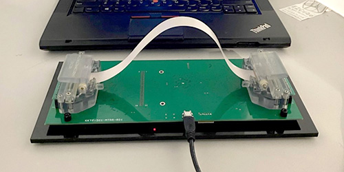
When dealing with surface-mounted components, the difficulty increases manifold. This is why technology like flex test fixtures are used to connect flex circuits with dense board assemblies. PCB test fixture manufacturers such as Z-Axis Europe are pioneering in this field and producing PCB testing fixtures that can cover thousands of test cycles and withstand wear and tear in the long run. This not only improves efficiency and testing speed (of the testing unit) thus bringing down the total process cost.
Z-Axis Europe uses elastomeric connectors and 3D-printed hard shells that create a favourable environment for advanced DUTs. An example of this type of test fixture is the Z-Axis FTF (Flex Test Fixtures).
Integrated Circuit Testers
IC testers are typically used to test individual components. They are not preferred to be used to test entire assemblies as they use a powered-down approach. IC testers were one of the first types of test fixtures available in the market.
Z-Axis Europe elastomeric connectors technology allows the design and build of advanced IC testers.
Customized Test Fixtures
Similar to ICTs, here a customized testing environment is created for the DUT or EUT in hand. This primarily involves electronic test signals and procedures enclosed in the same environment so that all the aspects of the DUT can be tested together and in a single go.
Z-Axis Europe has a notable offering in this type, which is used to test PCBs, electronic components, integrated chips (IC), SMD connectors, and packaging substrates (such as BGA sockets). The advantage of this type of test fixtures is that they can sustain thousands of test cycles and their environment can be modified according to the needs of the DUT.
Miscellaneous Testing
In addition to the primary types of test fixtures listed above, there are other types of testing such as manual inspection, computer-controlled automated testing, and optical inspection. In optical inspection, microscopic probes are used to check surface-level defects in both individual components and entire circuit boards. However, one major disadvantage in these methods is humen errors.
Then there are bare-board and functional tests that do not necessarily involve test fixtures. Such methods – also involving manual inspection – are usually preferred by small-scale manufacturers and DIYers.
PCB test fixture design
The contribution of PCB test fixture design in electronics has been tremendous. The recent arrival of modern technologies brought out by PCB test fixture manufacturers such as Z-Axis Europe has only improved the way we look at electronics testing. Such technologies help engineers simulate better test systems, thereby build better electronic systems. The ability to test and sort components prior to their assembly in a device is paramount to the success of the device and essential for the electronics industry in general.
Are you in need of a customized test fixture for your latest electronics project? Get in touch with Z-Axis Europe today.